11+ trim motor wiring 3 wire tilt trim diagram
Ignition easyautodiagnostics 1986 sentra. The best part of my repair was I had everything back in service in 3 days.
Common Outboard Motor Trim And Tilt System Wiring Diagrams Mastertech Marine
The owners game manual is a handy resource to have for general game operation game settings diagnostics switch lamp matrices fuse lists circuit boards and parts playfield assemblies.

. Electric Parts Components Add to cart. Started by Bjxds 10-13-2022 0509 PM. 20 Amps at 12V DC and 10 Amp at 24V DC.
Remove the tape from the PTT motor cables and the cable protector tube then slide the cable protector tube upward. Remove the screws securing the device to the mounting tray. 151 to determine if problem is power supply.
Best over the counter heartburn medicine. 1 Removed back - 6 screws 2 Removed dryer vent - 2 screws on top 3 on bottom 3 Popped the top open 4 Removed Front of dryer cabinet - 2 screws. Dual switches for JackPlateTiltTrim.
For correct assembly scribe an alignment mark on the field tube case and the brush holder. Pay particular attention to all Notes Cautions and Warnings. Tilt the rear of the device and mounting tray to a 30 angle.
Hot Rod Wiring - Diagram. Top Cover Maintenance Lift the power supply to expose the ground wire 2 and wiring harness 3. I pulled the gauge once again and set the dip switch to a 3 wire trim sender.
This Yamaha 69J-83672-11-00 TRIM SENDER fits the following. I used the 6Y5-83553-N0-00 gauge harness2 fuse kit and the 68F-82553-70-00 2 plug wire harness from motor to the 2 plug Tachometer. For complete control of engine trim and tilt trim tabs jackplates and other on board systems the innovative Paddle Trim system is the answer.
Wednesday 10 August. 827675A1 2-wire Connection. Tjnull oscp list 2022.
Remove all the components from the old chassis bed tilt. Instead of using a variable resistor for the gauge sensor they decided to use a varying voltage. Go to TILT TRIM RELAY TEST on p.
Power down the unit and unplug it. Make sure this fits by entering your model number. Mercruiser trim sender limit switch replacement Mercruiser Trim Sender Wiring Diagram - Drivenhelios.
New OEM Mercury Mariner 1996-2010 35-250 HP 3-Ram 2-Wire Tilt Trim System. This listing is for a New 1996-2010 OEM Mercury Mariner 35-250 HP 3-Ram 2-Wire Tilt and Trim System. I have a 2000 Johnson 50hp outboard motor and the tilt and trim will intermittently go down on its own.
12 wires with female 250 plugs crimped and installed. Last Post By. 35 - 225 HP Mercury 1985-92 Design 1 3-Ram Side Fill Integral Trim System 2-Wire Motor includes.
Tamasha movie download 480p filmyzilla. There is a tilt trim system Evinrude Ignition Switch Wiring Diagram crowleymarine parts. Yamaha tilttrim gauge wiring.
Connect the PTT motor leads 1 and then tighten the screws 2. Ptt Motor Disassembly POWER TRIM AND TILT 8-11 PTT MOTOR DISASSEMBLY Protector 1. Trim motor tilt wire parts harness outboard engines.
596 Bed UpDown Pedal Switch Refer to Figure 5-53 Elevating Base. Disassembling The Gear Pump Housing. Wiring Diagram ELECTRICAL COMPONENTS WIRING Read all of Section B and this section before attempting any procedure.
Dsg dual mass flywheel replacement Jun 20 2022 Thanks yall Johnson Evinrude Tilt Trim Single Ram System 1989-2004 40-50hp 438135 397532 750 Evinrude FICHT ETEC 90 115 135 150 175 200 hp Outboard Tilt Trim Unit If. First disconnect the power Trim and Tilt Motor. The cure is to.
16 Amps at 250V AC and 20 Amps at 125V AC. Comes as complete kit with wiring connectors and instructions. Thats why I dont think teleflex ever made a gauge for it.
Using a jumper wire apply 12 volts directly to the blue wire if your engine or drive unit is in the down position. Trim tilt wiring diagram yamaha outboard 1998 switch. The 5V comes from the yamaha trim guage the pink wire picks off a voltage as the wiper moves between the 5V reference end of the resitor to ground.
Must contain at least 4 different symbols. Replaces OEM numbers 826729A2 826729A6. SUZUKI OUTBOARD TRIM RELAY 38410-93J12 13216 11234 Sales Tax.
19 Main Wiring Harness Repair and Service Manual Page K-8. And one of these days was to consider just buying a new dryer. 14 Pictures about.
98 of products ordered ship from stock and deliver same or next day. This diagram was designed for 12 volt systems but can also be used for 6 volt systems. Hold the power trim and tilt unit in a vise using aluminum plates a on both sides.
IDM Members meetings for 2022 will be held from 12h45 to 14h30A zoom link or venue to be sent out before the time. Power Trim System Wiring Diagram 3 Cylinder Models Using COMMANDER. Etc and install them on the new chassis.
Started by GA198 10-10-2022 0756 PM. Hole size is 78 X 1-116 or 22mm X 27mm. View Profile View Forum Posts Private Message 10-11-2022 0848 PM.
It came with No instructions or wiring diagram. ASCII characters only characters found on a standard US keyboard. If anyone can lead me in the right direction it would be greatly appreciated.
ピアスに関するqa 販売しているピアスはすべて2個売りですか ピアスは2個売りとなっております 一部の特殊な形状のピアスや片耳用のピアスは1個売りとなっております. Had parts overnited and all parts fit and easy to replace. The return path for CDM 2 and The flywheel rotates the permanent magnets past 3 is through CDM 1 if 1 stator wire is discon- the capacitor charging coils causing the coils to pro- nected the engine will die the stator circuit is incom- duce AC voltage 260-320 volts.
Assembling The Power Trim And Tilt Motor BRKT Bracket unit Assembling the power trim and tilt Removing the reservoir motor 1. Slide the device and mounting tray toward the back of the trolley to remove them. For example 14 gauge wire will become 12 gauge 10 gauge will be 8 gauge etc.
11-18-2019 0434 PM. Schematics for each game are essential in tracing down connections to lamps switches and solenoids. If used for 6 volt make all the wires heavier by 2 gauges.
Run the bed up to the elevating bases top travel limit. On an Evinrude 70 hp outboard 4 stroke there is a tilt trim system Evinrude Ignition Switch Wiring Diagram crowleymarine parts 4602 cfmFind Ignition Switch with Key and Lanyard 5005801. Rating5 5.
This switch has three pins connect the yellow wire to pin 1 the purple wire to pin 2 and the white wire to pin 3. 4 Recommended Documentation 41 Manuals Schematics. McMaster-Carr is the complete source for your plant with over 700000 products.
6 to 30 characters long. Private caravan hire south east england.

1 8t 20v With Dsg Full Guide Tutorial Step By Step Vw Vortex Volkswagen Forum

8000 Carriers And Field Terminals Intelligent Platforms Pdf Electrical Connector Power Supply
Eaton Billows Electric Supply

Npboosted Jdm Parts Vehicle Supplier Diesel Auto Parts European Auto Parts
Tilt Trim Relay Wiring Diagram 2 Cool Fishing Forum
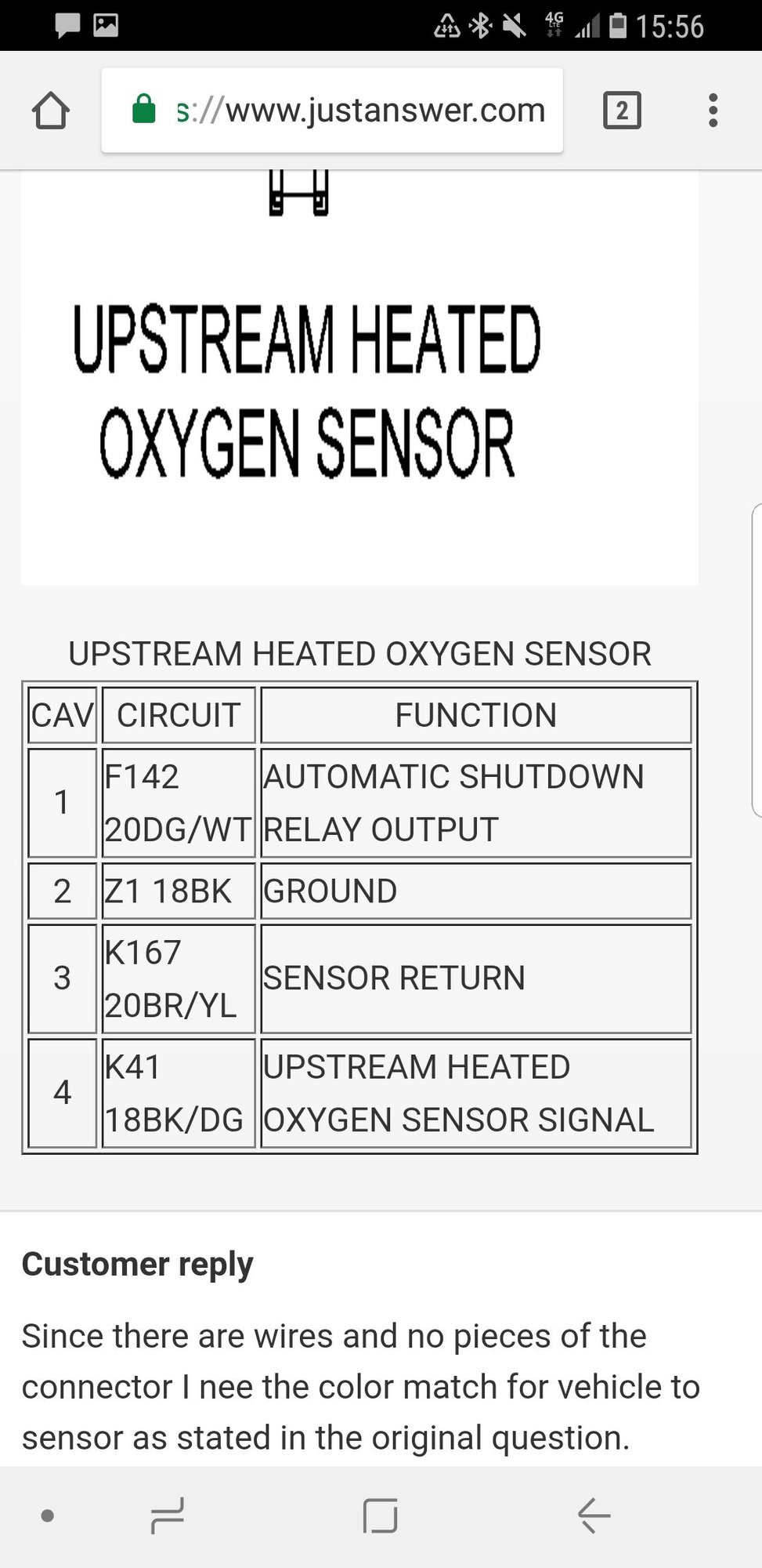
Upstream O2 Sensor Shenanigans Jeep Cherokee Forum

Vapor Logic Dri Steem
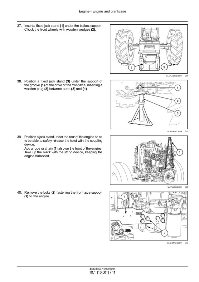
Case Ih Farmall 95 C Efficient Power Tractor Service Repair Manual P

Tilt And Trim Switch Wiring Diagram Great Johnson Power Tilt Outboard Electrical Diagram Boat Wiring

Injen 03 08 Mazda 6 2 3l 4 Cyl Polished Cold Air Intake Battleborn Speedshop

Car Won T Start S Type Jag Lovers Forums
通販銀座 自動車 バイクパーツ パーツ アクセサリー Ossir Uy
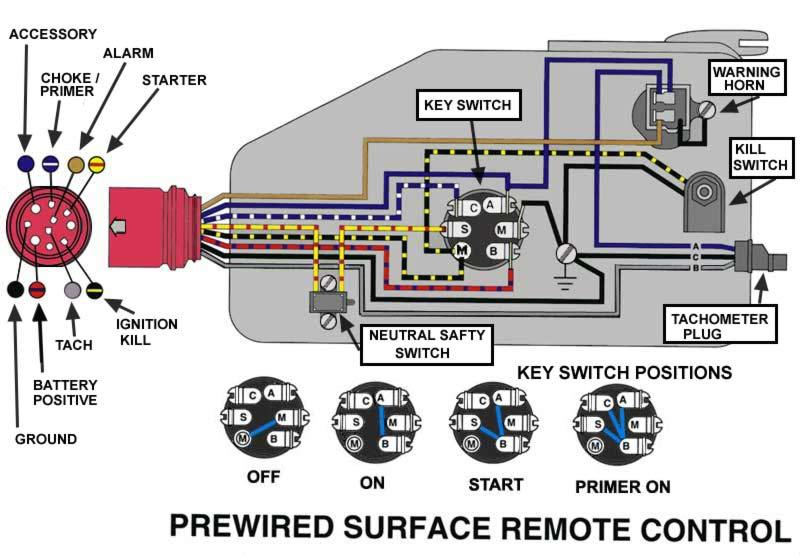
Common Outboard Motor Trim And Tilt System Wiring Diagrams Mastertech Marine

Razor Dirt Quad 24v Needs More Speed Electricscooterparts Com Support
Viewing A Thread 2 Wire Motor Trim Wiring Diagram

Pdf Service Manual Service Manual Section Lonestar And Prostar Chassis Built January 2007 And After Electrical Circuit Diagrams Model Lonestar Model Prostar Sotero Rodriguez Academia Edu

Awesome Evinrude Power Tilt Trim Wiring Diagram Mercury Outboard Outboard Diagram